- Supported Hardware
- Devices, command stations, networks, and protocols:
- Anyma DMX
- Arduinos
- Atlas Commander
- Bachrus
- BiDiB
- CAN Bus Networks
- CBUS®
- C/MRI
- CTI Electronics (Acela)
- CVP EasyDCC
- Dcc4Pc
- DCC-EX EX-CommandStation
- DCC++
- DCC Specialities
- Digi XBee
- Digikeijs / YAMORC
- Digitrax
- DMX 512 (Powerline)
- ESU ECoS
- Fleischmann
- Hornby
- Insteon (Powerline)
- LCC
- Lenz
- Lionel TMCC
- LocoNet
- Maple Systems
- Märklin CS2
- MERG
- Modbus
- MQTT
- MRC
- NAC Services RPS
- NCE
- Oak Tree Systems
- OpenDCC
- OpenLCB
- Pi Engineering RailDriver
- Powerline
- Protrak Grapevine
- QSI Quantum Programmer
- Raspberry Pi
- RFID Readers
- Roco
- SPROG DCC
- SPROG DCC Generation 5
- SRCP server
- TAMS Master Control
- TracTronics SECSI
- Uhlenbrock Intellibox
- Viessmann Commander
- Wangrow System One
- WiFi Throttles
- X10 (Powerline)
- XPressNet
- Zimo MX-1
- ZTC Controls
- Applications
- By the community of JMRI.org:
- Tools
- JMRI tools for working with your layout:
- Common Tools:
- Blocks:
- Routing and Control:
- Other:
- System-specific...
- Web server tools...
- Layout Automation
- Use JMRI to automate parts of your layout and operations:
Hardware Support: NCE
Supported Hardware
Command Station
JMRI supports five NCE layout connections:
- Power Pro (PowerHouse) via 9 pin serial cable like the PH1 and CS02
- Power Pro (PowerHouse) via network connection, but this requires additional hardware as a network to serial connection
- NCE USB Interface via a USB cable for the PowerCab, SB5 and Twin
- NCE Simulator, this allows for panel development while not connected to a layout.
- Power Pro (PowerHouse) via built in USB like the PH5 and CS03
- Serial
- Network Interface
- NCE USB
- Simulator
- PH5 USB
Limitations
A very small number of early (pre-2002) NCE Power Pro (PowerHouse) command stations have an "optional analog control circuit". (If you don't recall special ordering this, you probably don't need to read the rest of this paragraph!) In these, pins 5, 6, and 9 are used with an analog voltage as a separate throttle. If you have one of these command stations, a normal 9-pin serial cable will not work! You'll need to make a custom cable that just connects the "send data", "receive data" and "ground" pins. See your NCE manual for details.
If you use a NCE USB to talk to the PowerHouse series of command stations over the cab bus, it will only support the throttle functions and not the rest of the command station features.
Connecting
Settings
AIU (Input) Numbering
The NCE "AIU" device allows the NCE command station to check the status of inputs from the layout. These are referenced in JMRI as "Sensors" with names like "NS785". "NS" means "NCE Sensor", and 785 is the number of a specific sensor input.The sensor number can be found by using the following formula:
Sensor ID = (AIU Cab Address - 1) * 16 + (Pin Number On AIU) -1
For example: The AIU cab address is set to 50 and one of the BD20s is connected to pin 2. Therefore the Sensor ID would be:
Sensor ID = (50 - 1) * 16 + (2) -1
Sensor ID = 785
In the hardware address field of the Add Sensor window you can enter in the AIU cab address followed by the pin number separated by a semicolon. So for a sensor on AIU cab address 50, pin 2 you would enter the following: 50:2
Turnout Numbering
JMRI can access accessory decoders as NCE Turnouts and Lights. They are addressed using the same numbers that you would use on your NCE throttle to throw the accessory decoder. For example, if you can access turnout 21 from your throttle, JMRI would address it as "NT21" or just "21".Adding an item to the table
When you add an item to one of the tables, many times you only have to fill in the numbers
to have JMRI construct the complete system name.
Here's a summary, split up for outputs (eg. Turnouts) and inputs (eg. Sensors):
| In/Out | Entry | Meaning | makes System Name | Mask | Equivalent | Minimum | Maximum |
|---|---|---|---|---|---|---|---|
| i | 4:3 | AIU Cab 4, pin 3 | NS50 | cab: 1; pin: 1 | cab: 63; pin: 14 | ||
| i | 50 | AIU Cab 4, pin 3 | NS50 | cab: 1; pin: 1 | cab: 63; pin: 14 | ||
| o | 16 | Output (Turnout) 16 | NT16 | 1 | 2044 |
EPROM Versions
The NCE Power Pro command station uses an "EPROM" to contain it's software. NCE has made several of these available to it's users. JMRI has been updated to work with these as they come out. To determine which ROM version you have, go to the 'setup command station' menu on the ProCab. The first screen will show you the EPROM version currently installed.
- December 2004 EPROM - JMRI 1.6.1 or any JMRI 1.7 version or later should work fine.
- 2007 EPROM - you need JMRI 1.7.6 or later.
- Various "beta test" versions from early 2006 - ask NCE to send you an update to the 2007 EPROM, then use JMRI 1.7.6 or later
If you wish to use MONITORING for Turnout feedback, you must upgrade your Command Station to the Mar 1 2007A EPROM or newer. (For more information on turnout feedback, please see the feedback documentation page) The release in the first half of 2007 had a problem with odd turnout status. Every other odd accessory shared the same status bit. JMRI checks the revision number at startup, and will send a warning to the console window if it finds the early 2007 EPROM. If you're not sure if you have the latest, you can perform a simple test. First normal accessory 1 and 5 using the "Select Accy" button on your ProCab. Then using the "Select Accy" button, change accessory 1 to REV. Then check accessory 5, and if NOW = REV for accessory 5, you have the earlier revision with the known problem. If you have the early 2007 EPROM and wish to use MONITORING for feedback, contact NCE for an EPROM upgrade.
Wiring
Power Pro (PowerHouse) via serial cable

This section discusses JMRI's support for connecting to the NCE Power Pro and PowerHouse via the serial cable connector on their front panel.
- To connect your computer to an NCE Power Pro or PowerHouse system, you can usually just
connect the command station to the computer's serial port using a 9-pin serial cable. This
cable must be a 'straight through' extension cable and not a 'modem' type cable. On newer
computers there might not be a serial port, so you will need to use one of the computers
USB ports and a USB to serial adapter. See Via a USB to
Serial adapter for more information.
Many USB-Serial devices will still need a serial extension cable to connect the command station to the USB-Serial adapter.
Note that this is not the same thing as the NCE USB Interface, which is mostly for use with the PowerCab, not the Power Pro or Powerhouse system. - Then go to the preferences panel of a JMRI-based program. This opens automatically the first time a program is run, or you can select it from the "Edit" menu.
- Select "NCE" from the top selection box. You can then select the proper serial port in the second selection box.
- If given the option to select a baud rate choose 9,600 which is the default for NCE.
- Now confirm that the AIU broadcasts are disabled and the baud rate set in the NCE command station is the same as JMRI. These are the normal defaults for NCE. Use a ProCab to select "SET CMD STATION" by pressing the PROG/ESC button 5 times. Then press the ENTER button 14 times to determine if AIU broadcasts are disabled. Press 0 to disable. Now press the ENTER button once more to select the baud rate. Press 1 to set the baud rate to 9,600, and press PROG/ESC to exit.
- Select the version of EPROM present in your command station, either "2004 or earlier" or "2006 or later". See below for more information on this.
- Click "Save". You'll be asked if it's OK for the program to quit, click "Yes".
- Restart the program. You should be up and running.
- If not see the Troubleshooting section below.
For reliable operation, we recommend that you disable "AIU broadcast", and set the baud rate to 9,600. These are the normal defaults for NCE. Both of these parameters can be found in your NCE user's manual under "Setup Command Station".
Power Pro (PowerHouse) via Network
Instead of connecting a serial cable from your computer to a Power Pro, you can also connect JMRI to your Power Pro via a network connection and a serial-network adapter. This will let you, for example, connect a computer in one room to a layout in another without having to run a long serial cable.(There's also a general page on the use of serial-network adapters, also known as terminal servers)
- Connect your serial-network adapter to your NCE Power Pro or PowerHouse system using a 9-pin serial cable.
- Configure the serial-network adapter to use the same baud rate set as the NCE command station. 9600 baud is the normal default for NCE. To confirm this and the AIU broadcast setting, use a ProCab to select "SET CMD STATION" by pressing the PROG/ESC button 5 times. Then press the ENTER button 14 times to determine if AIU broadcasts are disabled. Press 0 to disable. Now press the ENTER button once more to select the baud rate. Press 1 to set the baud rate to 9,600, and press PROG/ESC to exit.
- Then go to the preferences panel of a JMRI-based program. This opens automatically the first time a program is run, or you can select it from the "Edit" menu.
- Select "NCE via network" from the top selection box.
- In the "Server hostname" box, enter the Internet name or Internet address numbers for your serial-network adapter. In the "Port number" box, enter the port on the serial-network adapter to be used.
- Select the version of EPROM present in your command station, either "2004 or earlier" or "2006 or later". See above for more information on this.
- Click "Save". You'll be asked if it's OK for the program to quit, click "Yes".
- Restart the program. You should be up and running.
- If not see the trouble shooting section below.
For reliable operation, we recommend that you disable "AIU broadcast", and set the baud rate to 9,600. These are the normal defaults for NCE. Both of these parameters can be found in your NCE user's manual under "Setup Command Station".
NCE USB Interface
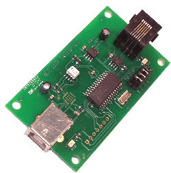
The NCE USB Interface can be connected to all NCE systems, Power Cab, SB3 (SmartBooster), SB5, Twin or Power Pro. You must select the correct system from the preference menu for reliable operation.
- On most computers, you'll need to install a driver for the CP201x USB to
UART Bridge VCP used in the NCE USB Interface.
- Windows driver
- Mac OS X driver
- Linux drivers
- If one of the above links doesn't work, you can perhaps find the needed driver on the support web site for SiLabs chips.
- Now go to the preferences panel of a JMRI-based program. This opens automatically the first time a program is run, or you can select it from the "Edit" menu.
- Select "NCE USB" from the top selection box. You can then select the proper serial port in the second selection box.
- If given the option to select a baud rate choose 9,600 which is the default for NCE.
- Select the type of system that you are connecting the USB adapter to, Power Cab, SB3, or Power Pro (PowerHouse). The default is Power Cab, no jumpers installed.
- Now confirm that the adapter's baud rate is also set for 9,600 by removing jumper #1. Installing jumper #1 sets the baud rate to 19,200.
- The series of radio buttons labeled "GUI style" allows you to select how the program will look. "Metal" is the native Java look available on all types. Other choices will vary with your computer type. "CDE/Motif", "Windows", and "Mac OS X" look native on Linux, Windows, and Mac OS X respectively.
- In the bottom selection box, you can pick the default programmer format. You can override this each time you open the programmer, so this is here just for convenience.
- Click "Save". You'll be asked if it's OK for the program to quit, click "Yes".
- Restart the program. You should be up and running.
- If not see the trouble shooting section below.
To connect your computer using a NCE USB Interface, you will need in addition to the USB
Adapter, a USB A to USB B cable to connect the Adapter to your computer and a Throttle cable
to connect the adapter to your NCE system. The Throttle cable may be another of the 'coily
cords' that came with another hardware throttle or the PowerCab system.
It is important to use a straight through RJ11 cable and not a crossover like some phone
cables. Look at the end connectors to make sure that the colors are in the same order. You
can use a RJ12 cable with six conductors in place of the RJ11 because it's only the four
center conductors that are used, but it must also be a straight through cable.
NOTE: If using a PowerCab, you must have firmware version 1.28c or later installed on
that.
The connection order is also important:
- Plug in the cab-bus side and power up the attached PowerCab
- Once the PowerCab is up and working, then plug the USB cable into the computer.
NCE USB Interface Limitations
The NCE USB Interface doesn't support all of the current JMRI features and functions. Some of the restrictions are based on the type of system the USB Adapter is connected to. The USB version 6.* can't get information from AIUs, so they can't be used to get feedback from the layout. The USB 7.* version when connected to a system with the 1.65 or higher firmware (PowerCab, SB5, Twin) the AIU cards can be used, but with restricted cab numbers as in the system manual. The turnout feedback mode MONITORING isn't available when using a USB, and the Clock functions found in tools are also not available. The USB when connected to a Power Pro system doesn't support any type of loco programming, and when connected to a SB3 only operation mode (no program track) is available for loco programming. Most functions and features that are not supported by the NCE USB Interface are disabled or grayed out in the JMRI program.
USB Adapter Limitation Summary
- All systems:
- No Turnout MONITORING, No Clock functions.
- No Ops Mode Signal (Extended Accessory) programming.
- SB3 and SB5:
- No programming track support, Ops Mode programming only.
- Power Pro:
- No programming of any kind.
- No AIU support.
- AIU Support:
- USB below 7.* version, no AIU support.
- USB version 7.* and above, system with version 1.65 and above firmware, AIU supported.
NCE PowerHouse with built in USB
This is the next generation of large layout command stations. The first is the PH5 and was released late in 2023. Internally the command station is new and uses a completely different memory map from the older NCE serial systems. The CS03 was released around May 2024 and is a functional replacement for the CS02.
Troubleshooting
When the connection to your NCE is okay and your NCE system is powered up, after starting PanelPro you should see the following JMRI Startup screen:
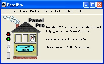
If your are using JMRI v 2.1.2 or newer and the screen looks like the above, congratulations; you are up and running. The startup screen for DecoderPro is similar to PanelPro's.
If you have the following control panel with the words "NCE: ERROR SERIAL USING COMx" in the right center of the panel:
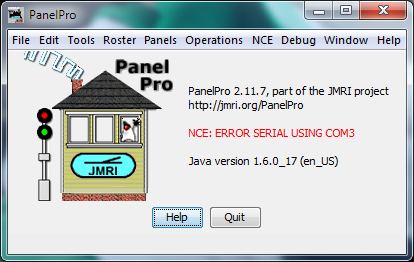
you have a problem that needs your attention. The following is a list of potential issues
that might help you resolve your problem:
- Confirm that your NCE Command Station is powered up.
- Check your cables, make sure they are installed correctly.
- If there was more than one "Serial Port" to choose from in the JMRI preferences menu, try the others.
- Recheck the baud rates selected, make sure both JMRI and the NCE Command Station are set to the same rates.
Using the System Console
JMRI provides connection information via the system console. You can find the system console under the main menu header "Help" then "System Console...". Below is an image of the console window when the program is operating normally. Note that the window size has been adjusted so we can read it a bit more easily.
![]()
If you're having problems, the console window can look like the one below:
![]()
To help you better understand what might be happening and to possibly resolve your problem we'll explain some of the warning and error messages displayed in the above console window.
The very first messages are information message labeled "INFO". The first message occurs at time "0" which can be found at the left side of the message. The next "INFO" message states where this log file is stored. The next info provides the version of JMRI and JAVA that you are using. And the last info message provides the communication port that you've selected in preferences, along with the baud rate or the speed of your connection.
The first warning message states that there was a timeout to message "AA". During startup, JMRI checks to see if your Preferences match those in the NCE command station. Message "AA" requests the EPROM revision of the command station. The response is normally three characters, something like "6.2.1". A timeout means that JMRI asked for something and the command station didn't respond. When the connection is correct and the system is powered up, you should not see any timeout messages.
The next warning message states that because there was a timeout, the program didn't get the information requested from the command station. The next messages continue as the program tries every 10 seconds to read the EPROM revision by issuing the "AA" command. You can try and trouble shoot your connections knowing that every 10 seconds JMRI will retest to see if you've fixed the problem.
Whenever JMRI detects a problem with the connection or NCE command station, it will request the EPROM revision to see if the connection and command station is still operational. So if you see timeouts and "AA" commands you have either poor or failed connection, or a powered down or failed command station.
Using a Loop Back Serial Cable
You can confirm that you've selected the correct port and that your cable is okay by connecting the male connector pins 2 and 3 with a small jumper wire. Doing this will loop the message "AA" back to JMRI via the Receive line. The console messages should change and look like the ones in the following image:
![]()
JMRI NCE Tools
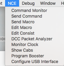
When JMRI is connected to a layout via this system, an NCE menu is shown:
- Command Monitor

-
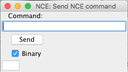
Send
Command
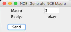
- Send Macro
-
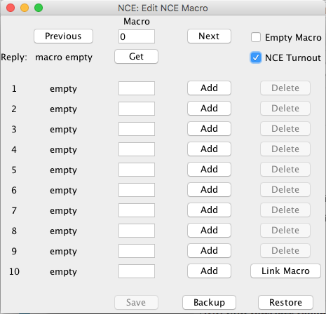
Edit
Macro
-
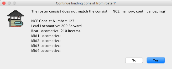
Edit
Consist

-
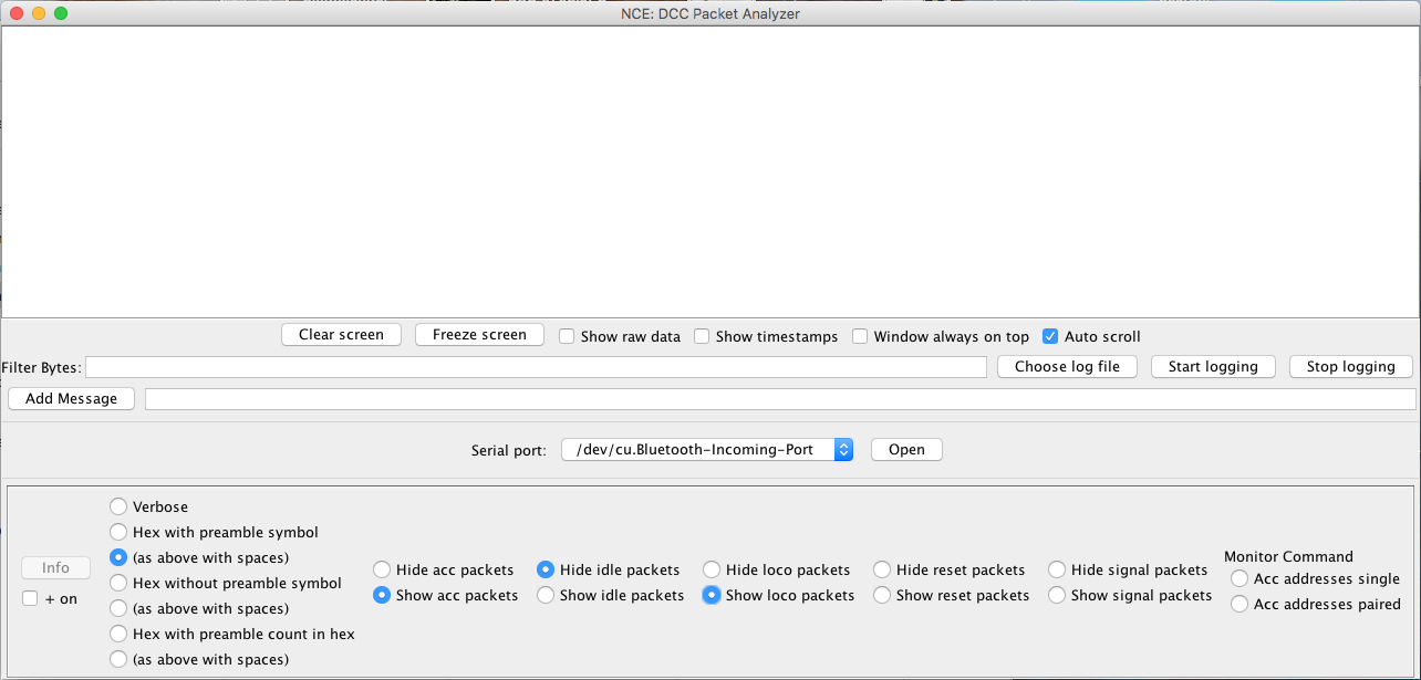
DCC Packet
Analyzer
-
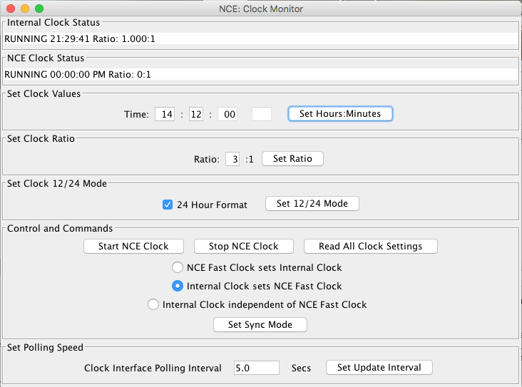
Monitor
Clock
- Show Cabs

- Program Booster

- Configure USB Interface
Documentation
JMRI Help
If you are having problems, you should try the JMRI users group to contact other JMRI users that can help you out.