- JMRI Gallery
- People have used JMRI to do some great things for the model railroad community
- Cornwall RR
- Dispatcher Panel by Nick Kulp
- Modular Layouts
- JMRI used during a Modules Meeting
- SP Shasta Route
- Run using PanelPro by Otis McGee
- JMRI Clinics
- Archived JMRI presentations on NMRA National Conventions and elsewhere
- JMRI User Gallery
- People have used JMRI to do some great things for the model railroad community.
Our Gallery page highlights some of these. - Apps using JMRI
- Showcase of third party apps that connect to JMRI
- JMRI Code Visualisation
- Get an impression of the parts that make up JMRI Code
- Applications
- By the community of JMRI.org:
JMRI Gallery
This page highlights some of the neat things people have done with
PanelPro applications
Many PanelPro users have each come up with their own PanelPro application, ranging from simple to complex:
Modular Signals in the UK
The Essex Belt Lines group is using JMRI to add signalling, including CTC, to their large modular layouts. There was a nice writeup in the Fall 2016 issue of the OPSIG BR eNews.OWNry
Kent Williams'
Oregon Washington Navigation & Railway
(now dismantled) used PanelPro for its signal controls and
CTC
dispatcher panel.

Cashaway Valley Railroad
Jim Thompson is using PanelPro to make a dispatcher's panel for his Cashaway Valley Railroad. Watch this YouTube Video.Cornwall RR
Well over a decade ago, Nick Kulp already created a program to drive his Cornwall RRQuaker Valley
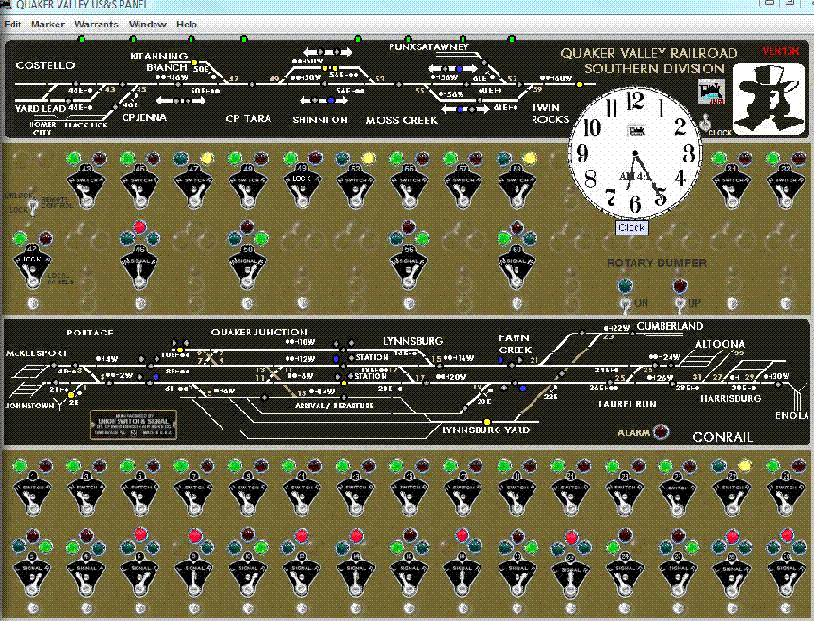
Bob Bucklew built a realistic CTC panel for his Quaker Valley Railroad.
He's created a very nice series of web pages on
how it was done.
Bloomfield & Oakland RR
Alan Huberty created a multi-screen control panel for his Bloomfield & Oakland Railroad.

Shasta Route

The goal of Otis McGee's SP Shasta Route is prototypical fidelity to 1952 operations. At the time, the railroad was run from a CTC machine at the dispatcher's office in Dunsmuir, CA (see photo to right). To recreate that, Otis has installed a rebuilt United Switch and Signal CTC machine on his railroad. PanelPro controls the machine and provides CTC control for the layout via a large seven-node C/MRI installation.
Durenver & Silverton RR
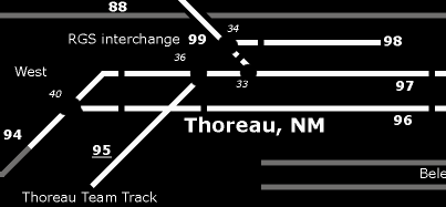
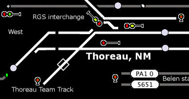
Egbert Broerse's Durenver & Silverton Railroad panel was made using Panel Editor and is displayed on a compact LCD monitor by JMRI PanelPro 2.4.1 on OSX 10.4.6, the last version supported by the MacMini hardware.The graphics on the panel match a generic (US-built) Entrance-Exit (NX) CTC machine, in use from 1950 until the mid nineties. However, most turnouts are operated with an Individual Function Switch (IFS); see the Signaling Wiki.
The NX CTC machine in Eindhoven, The Netherlands (photo © Nico Spilt)
Egbert started by drawing a compact track schematic in 4 pt white lines on a black background. Location names and block boundaries were added to help in the orientation of the dispatcher. Icons from the Small LED schematics group were added to show track occupancy and Medium LED icons display and control the current state of lighting etc. Turnouts in hidden trackage are monitored using Infrared detectors, shown on the panel, supported bij audio signals produced by JMRI. Later, signals were added on the layout as well as to the panel (below, center). All logic is controlled as Signal Mast Logic following a customized Rio Grande 1965 Rule Book signal definition. Physical control panels on the layout fascia sport the same graphic style, be it black on yellow (below, right; 3 images © EJB as CC BY-NC-SA)).
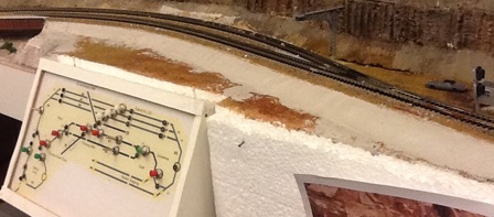
Czechoslovak State Railways – Elektrosignal Praga
Electromechanical interlocking equipment wikipedia is widely used in Europe and North America. The Siemens & Halske 1912 model was first put into operation in 1894 in Prerau at The Emperor Ferdinand Northern Railway in the Austro-Hungarian Empire (now Přerov in the Czech Republic). In later years, this device was manufactured by more than one company.
JMRI provides a look of appearance produced by Elektrosignal Praga – ESP for Czechoslovak State Railways – ČSD. Description of deployment in PanelPro is here.

Czechoslovak State Railways – AŽD-71
AŽD-71 is relay interlocking system produced by Automatizace železniční dopravy Praha – AŽD. It was developed in Czechoslovakia in the 1960s. The AŽD-71 system was deployed from 1970 to 1996 as the main relay interlocking system in the network Czechoslovak State Railways – ČSD.
JMRI provides a look of appearance AŽD-71 for Czechoslovak State Railways – ČSD. Description of deployment in PanelPro using Layout Editor is available here.

Operation of JMRI Layout Editor with relay interlocking AŽD-71 on modular layout https://youtu.be/2yM_s5HZbE8.
Czechoslovak State Railways – JOP
JOP – Jednotné Obslužné Pracoviště – Unified Control Place – is a standardized user interface for interlocking systems used in Czechoslovakia. For first time it was used in station Dřísy in 1991. Currently, the JOP user interface is standardized and used with interlocking systems from various manufacturers such as AŽD Praha, AK signal Brno or STARMON Choceň.
JMRI provides a JOP style look for Czechoslovak State Railways – ČSD and his successors. A tutorial for Control Panel Editor and Warrants with JOP is available here.
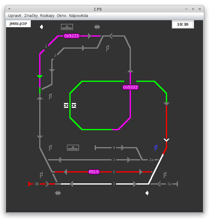
Operation of JMRI Warrants with Control Panel Editor with JOP style on layout https://youtu.be/NM7S6jYtH_o.
Innovative uses of the JMRI Libraries
Crandic Dispatcher
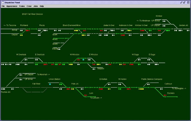
The Cedar River and Iowa Central Railway (Crandic) has a great "Dispatching on the Crandic" video, along with several others, available for download. The Crandic's control program and dispatcher panel called CATS was built by Rodney Black on top of the JMRI libraries. He's kindly made it available as open-source software to anybody who wants to use it.Fall River Division
CATS is also used on John Parker's BNSF Fall River Division for their dispatcher's panel.