Adding Signal Masts
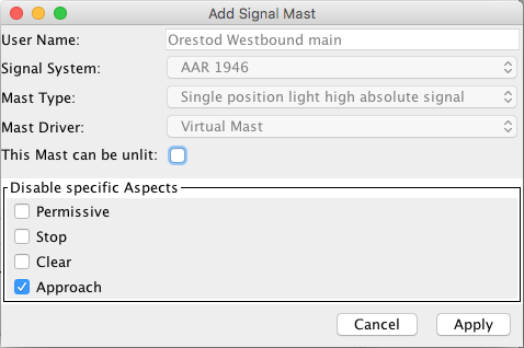
Signal Masts are configured using one of the available Signaling Systems, and the Signal Mast Types supported within that system.
In the Add/Edit Signal Mast panel, after entering a User Name for the new
Signal Mast, from the pop-up menu select the JMRI Signal System the Signal Mast is to be
based upon.
Next select one of the Signal Mast models available in the selected Signal System e.g. "3
Aspect Signal with Call On".
The third pop-up menu on the Add Signal Mast panel lets you select one of six different
Signal Mast Driver types depending upon the hardware being used. More on those in the next
section.
Options common to (nearly) all Driver types include:
- This Mast can be Unlit: checking this box allows JMRI to turn off the mast, using an extra instruction such as an output state. When configuring a mast that can be unlit, the same aspect ID has to be entered in both the field at the top as the Aspect line below for the correct appearance to be displayed in all possible scenarios.
- Disabled: checking this box for an Aspect will gray out the options and have JMRI skip it when changing the state of this mast
- Copy Aspects from Mast: DCC, LNCP and Matrix drivers let you copy the settings for a new mast to match an already configured mast. Of course the User Name and outputs should be unique, so they are not copied.
When ready, click Create new (or Apply when editing an existing mast configuration).
Signal Mast Driver types
- Signal Head Controlled
-
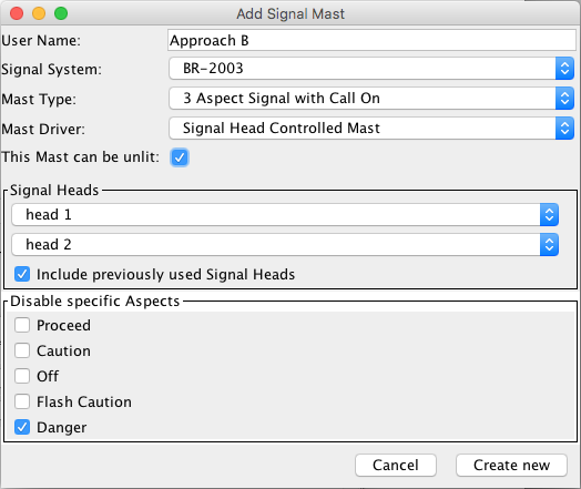
Individual Signal Head objects are used to represent each Signal Head on the Signal Mast.
Each Signal Head object will then deal with handling the changing of its Appearance depending upon the state of the Signal Mast and the position of this Signal Head relative to other Heads.
For each head that has been defined in the Signaling System for the selected Signal Mast type, a drop down box will appear for you to select the JMRI Signal Head that will control that head on this Signal Mast. - Turnout Controlled
-
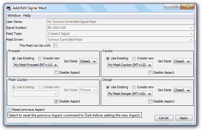
This Driver type is for specific hardware that can control the whole Appearance of a Signal Mast based upon the setting of one or more Turnouts.
Each aspect can be configured to send the Thrown or Closed Turnout state.
Leave theReset Previous Aspect
unchecked if the Turnout event also clears previous aspects on a remote module. - Virtual
-
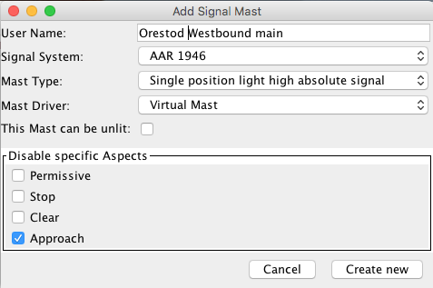
This mast does not directly control any hardware relating to a Signal Mast.
It is ideal for locations where a physical mast would not be present on the railroad, such as an End Bumper/Buffer Stop, or to mark the end of a signaling section of track and the beginning of Dark Territory.
No commands are sent to the layout, so there's no connection to choose. - DCC Signal Mast Decoder
-
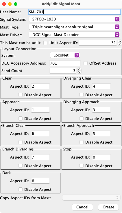
This Driver type is for an accessory decoder that can drive the Signal Masts natively and supports the NMRA Extended Accessory Protocol S-9.2.1.
Enter the Aspect numbers configured in your decoder for each Aspect. The default values for the ID of each Aspect as defined in the Signaling System definition can be over-written. If the signaling system does not have predefined IDs, enter values from 0 to 31. Use 0 for Stop or its equivalent. The Copy Aspects IDs from Mast option at the bottom can be used to populate the IDs for subsequent masts that are the same type.
Decoders like the Signalist SC1 have Signal Mast types preconfigured and you just select the correct table with a CV and get the Aspect numbers from the manual.
since 4.25.4Some DCC Signal decoders, such as the NCE Light-It, use an alternate addressing scheme. The OffSet Address checkbox is used to enable alternate addressing.
When the Unlit option is selected, an aspect ID has to be selected that has been configured to set the mast lights off. The default value is 31. If the signal system includes a Dark or Unlit aspect and it sets the lights off, that ID could be selected for the Unlit option. Note: Unlit is a separate process but it can use the same ID.
- LNCP Signal Mast Decoder
- Like the previous option, the LocoNet Control Point (LNCP) Driver type needs only a decoder ID and optionally Aspect ID's to drive a RR_Cirkits LNCP module.
- Output Matrix
-
since 4.6
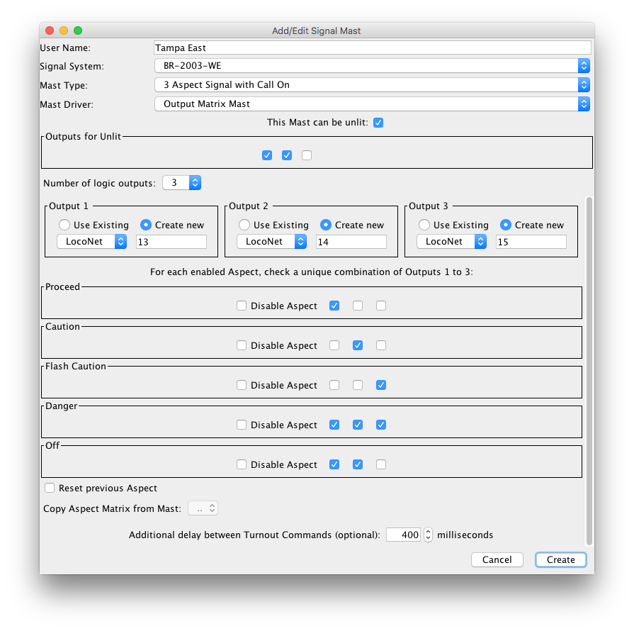
This Driver creates a truth table to set from 1 to 6 outputs per Aspect. To define 8 different patterns, you will need at least 3 on/off fields.
The Output Matrix driver was developed to connect decoders configured to connect and drive signals, like a Digirails DR4018 with built in aspect mapping set to match your JMRI signal system and mapping.
When selected from the Driver drop down list, the panel lets you:- Set the number of logic outputs (3 in the screen shot, select from the
Number of logic outputs drop down list).
The panel is redrawn when you change this number, showing as many... - Output selection boxes. Select or create Turnouts as binary outputs.
- For each Aspect, Checkboxes allow you to set the corresponding position of the outputs, hence the Matrix name
- since 4.15.7Set a mast-specific delay that is applied between every output command
The output names and the Unlit row can be changed later on by clicking the Edit button in the Signal Mast table. It's not possible to change the number of outputs in the matrix once a mast has been saved. - Set the number of logic outputs (3 in the screen shot, select from the
Number of logic outputs drop down list).
Click Create new to add the new Mast and return to the Signal Mast Table.
Back to the Signal Mast Table help page.
Thanks and congratulations to all who contributed! Contact us via the JMRI users Groups.io group.
Copyright © 1997 - 2024 JMRI Community. JMRI®, DecoderPro®, PanelPro™, DispatcherPro™, OperationsPro™, SignalPro™, SoundPro™, LccPro™, TrainPro™, Logix™, LogixNG™ and associated logos are our trademarks. Additional information on copyright, trademarks and licenses is linked here.
View the